Showing posts with label digital. Show all posts

Tuesday, November 18, 2014

Digital Thermometer 0 100 0°Celsius

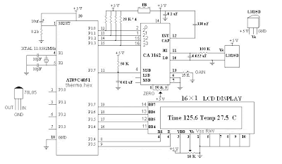
Digital Thermometer 0-100.0 ° C is a digital thermometer that operates in mode temperature measurement in Celsius (° C). Digital Thermometer 0-100.0 ° C in this article using the form data processing microcontroller AT89C4051. Temperature sensors used in Digital Thermometer 0-100.0 ° C. This temperature sensor LM35D. Digital Thermometer 0-100.0 ° C. It uses the temperature measurement data viewer in the form of 1 line LCD viewer. Digital Thermometer 0-100.0 ° C. It can display the temperature measurement data with a resolution of 0.1 ° C.
Digital Thermometer 0-100.0 ° C

Digital


Digital Thermometer 0-100.0 ° C. These temperature sensors make use of LM35D as temperature sensing. In Digital Thermometer 0-100.0 ° C. This temperature sensor measurement data this LM35D (Level Voltage) is then converted into 4-bit binary data using the ADC CA3162. Then the 4-bit data from ADC CA3162 which is a measurement of data if the temperature is in the AT89C4951 microcontroller so that it becomes an operating principle of temperature measurement based on digital thermometers. In the final stage of the Digital Thermometer 0-100.0 ° C. These data digitla adlah appearance temperature measurement, using digital data viewer of the LCD 1 line.
Read More..

Digital visitor counter

Digital visitor counter is a reliable circuit that takes over the task of counting Number of Persons/ Visitors in the Room very Accurately. When somebody enters into the Room then the Counter is Incremented by one and when any one leaves the room then the Counter is Decremented by One. The total number of Persons inside the Room is displayed on the seven segment displays.The microcontroller do the above job it receives the signals from the sensors, and this signals operated under the control of software which is stored in ROM.

Digital visitor counter

Read More..

Wednesday, November 5, 2014

Two Button Digital Lock

This very simple circuit of two button digital lock. Now here’s a digital lock unlike any other, as  it has only two buttons instead of the usual  numeric keypad. The way it works is as simple  as its keypad. Button S1 is used to enter the  digits of the secret code in a pulsed fashion-i.e. the number of times you press the but-ton is determined by the digit to be entered.  A dial telephone uses the same type of coding (now maybe there’s an idea?). Press four  times for a 4, nine times for a 9, etc. Pressing button S2 indicates the end of a digit. 

Two-button Digital Lock Project Image:

Digital 

For example, to enter the code 4105, press  S1 four times, then press S2, then S1 once, S2  once, then without pressing S1 at all, press S2  again, then finally S1 five times and S2 once  to finish. If the code is correct, the green LED D1 lights for 2 seconds and the relay is energised for 2 seconds. If the code is wrong, the  red LED D2 lights for 2 seconds, and the relay  is not energised. To change the code, fit a jumper to J1 and  enter the current code. When the green LED  D1 has flashed twice, enter the new 4-digit  code. D1 will flash three times and you will  need to confirm the new code. If this confirmation is correct, D1 will flash four times.  If the red LED D2 flashes four times, some-thing’s wrong and you’ll need to start all over  again. To finish the operation, remove the  jumper and turn the power off and on again the digital lock is now ready for use with  the new code.

Two-button Digital Lock Circuit diagram :
Digital


The software can be found on the webpage for the project [1]. Don’t forget to erase the microcontroller’s EEPROM memory before  programming  it,  so  you  can  be  sure  that  the  default  code  is  1234  and  not  some -thing unknown that was left behind in the  EEPROM. A little exercise for our readers: convert this  project into a single-button digital lock for  example, by using a long press on S1 instead  of pressing S2 to detect the end of a digit.
 
Author : Francis Perrenoud  - Copyright : Elektor

Read More..

Thursday, September 11, 2014

Digital Mains Voltage Indicator

Digital Mains Voltage Indicator Circuit diagram. Continuous monitoring of the mains voltage is required in many ap-plications such as manual volt-age stabilisers and motor pumps. An ana-logue voltmeter, though cheap, has many disadvantages as it has moving parts and is sensitive to vibrations. The solidstate voltmeter schema described here indicates the mains voltage with a resolution that is comparable to that of a general-pur-pose analogue voltmeter. The status of the mains voltage is available in the form of an LED bar graph. Presets VR1 through VR16 are used to set the DC voltages corresponding to the 16 voltage levels over the 50-250V range as marked on LED1 through LED16, respectively, in the figure. The LED bar graph is multiplexed from the bottom to the top with the help of ICs CD4067B (16-channel multiplexer) and CD4029B (counter). The counter clocked by NE555 timer-based astable multivibrator generates 4-bit binary ad-dress for multiplexer-demultiplexer pair of CD4067B and CD4514B. 

Digital Mains Voltage Indicator Circuit diagram

Digital

.

Digital Mains Voltage Indicator Circuit Diagram

The voltage from the wipers of pre-sets are multiplexed by CD4067B and the output from pin 1 of CD4067B is fed to the non-inverting input of comparator A2 (half of op-amp LM358) after being buff-ered by A1 (the other half of IC2). The unregulated voltage sensed from rectifier output is fed to the inverting input of com-parator A2. The output of comparator A2 is low until the sensed voltage is greater than the reference input applied at the non-inverting pins of comparator A2 via buffer A1. When the sensed voltage goes below the reference voltage, the output of com-parator A2 goes high. The high output from comparator A2 inhibits the decoder (CD4514) that is used to decode the out-put of IC4029 and drive the LEDs. This ensures that the LEDs of the bar graph are ‘on’ up to the sensed voltage-level pro-portional to the mains voltage.
The initial adjustment of each of the presets can be done by feeding a known AC voltage through an auto-transform and then adjusting the corresponding pre-set to ensure that only those LEDs that are up to the applied voltage glow. 

EFY note.  It is advisable to use ad-ditional transformer, rectifier, filter, and regulator arrangements for obtaining a regulated supply for the functioning of the schema so that performance of the cir-cuit is not affected even when the mains voltage falls as low as 50V or goes as high as 280V. During Lab testing regu-lated 12-volt supply for schema operation was used.)


Author : Pratap Chandra Sahu - Copyright : EFY
Read More..

Monday, September 1, 2014

Digital Fan Regulator


Digital Fan Regulator Circuit diagram. The schema presented here can be used to control the speed of  fans using induction motor. The speed control is nonlinear, i.e. in steps. The current step number is displayed on a 7-segment display. Speed can be varied over a wide range because the schema can alter the voltage applied to the fan motor from 130V to 230V RMS in a maximum of seven steps.  The triac used in the final stage is fired at different angles to get different voltage outputs by applying short-dura-tion current pulses at its gate. For this pur-pose a UJT relax-ation oscillator is used that outputs sawtooth waveform. This waveform is coupled to the gate of the triac through an optocoupler (MOC3011) that has a triac driver output stage. 

Pedestal voltage control is used for varying the firing angle of the triac. The power supply for the relaxation oscillator is derived from the rectified mains via 10-kilo-ohm, 10W series dropping/limit-ing resistor R2.  The pedestal voltage is derived from the non-filtered DC through optocoupler 4N33. The conductivity of the Darlington pair transistors inside this optocoupler is varied for getting the pedestal voltage. For this, the positive sup-ply to the LED inside the optocoupler is connected via different values of resistors using a multiplexer (CD4051). 

Digital Fan Regulator Circuit diagram:

Digital
 
Digital Fan Regulator Circuit Diagram

The value of resistance selected by the multiplexer depends upon the control in-put from BCD up-/down-counter CD4510 (IC5), which, in turn, controls forward bi-asing of the transistor inside optocoupler 4N33. The same BCD outputs from IC5 are also connected to the BCD-to-7-seg-ment decoder to display the step number on a 7-segment display.  NAND gates N3 and N4 are config-ured as an astable multivibrator to produce rectangular clock pulses for IC5, while NAND gates N1 and N2 generate the active-low count enable (CE) input using either of push-to-on switches S1 or S2 for count up or count down operation, respectively, of the BCD counter. 

Optocoupler 4N33 electrically isolates the high-voltage section and the digital section and thus prevents the user from shock hazard when using switches S1 and S2. BCD-to-7-segment decoder CD4543 is used for driving both common-cathode and common-anode 7-segment displays. If phase input pin 6 is ‘high’ the decoder works as a common-anode decoder, and if phase input pin 6 is ‘low’ it acts as a common-cathode decoder.  Optocoupler 4N33 may still conduct slightly even when the display is zero, i.e. pin 13 (X0, at ground level) is switched  output pin 3. To avoid this problem, adjust preset VR1 as required using a plastic-handled screwdriver to get no output at zero reading in the display.
Read More..