Friday, December 12, 2014
Plus and Minus DC Power Supply

This is a classic example of a regulated DC power supply that produces both a positive 15v and a negative 15v from a 20vac wall adapter.
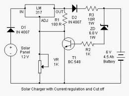
Solar Battery Charger Circuit Schematic

Here is a solar charger circuit that is used to charge Lead Acid or Ni-Cd batteries using the solar energy power. The circuit harvests solar energy to charge a 6 volt 4.5 Ah rechargeable battery for various applications. The charger has Voltage and Current regulation and Over voltage cut off facilities.
Power Amplifier
300w Sub-woofer Power Amplifier - High power amps are not too common as projects, since they are by their nature normally difficult to build and are expensive.
LM3886 Power Amplifier - The LM3886 is a high-performance audio power amplifier capable of delivering 68W of continuous average power to a 4 ohm load and 38W into 8 ohm load.
2.3 GHz Power Amplifier - 2 schematic which contains prototype and real one.
20 Watt Class-A Power Amplifier - This amp uses the basic circuitry of the 60W power amp but has been modified for true Class-A operation.
20 Watt / Channel Stereo Power Amplifier - This project is based almost directly on the typical application circuit in the National Semiconductor specification sheet.
Simple Audio Power Amp - This simple audio power amplifier was originally designed for a circuit board workshop conducted by the OSU IEEE Student Group.
Death of Zen (DoZ) - A New Class-A Power Amp - This project design specifically for headphones.
Simple Current Feedback Power Amplifier - The first version of the amp uses a single power supply and capacitor coupled speaker.
Single Chip 50 Watt / 8 Ohm Power Amplifier - This project is based almost directly on the typical application circuit in the National Semiconductor specification sheet.
Soft-Start Circuit For Power Amps - The circuit presented in the website is designed to limit inrush current to a safe value.
170W Audio Power Amplifier - Suitable for self-powered speakers, sub-woofers and quality car boosters.
Read More..
LM3886 Power Amplifier - The LM3886 is a high-performance audio power amplifier capable of delivering 68W of continuous average power to a 4 ohm load and 38W into 8 ohm load.
2.3 GHz Power Amplifier - 2 schematic which contains prototype and real one.
20 Watt Class-A Power Amplifier - This amp uses the basic circuitry of the 60W power amp but has been modified for true Class-A operation.
20 Watt / Channel Stereo Power Amplifier - This project is based almost directly on the typical application circuit in the National Semiconductor specification sheet.
Simple Audio Power Amp - This simple audio power amplifier was originally designed for a circuit board workshop conducted by the OSU IEEE Student Group.
Death of Zen (DoZ) - A New Class-A Power Amp - This project design specifically for headphones.
Simple Current Feedback Power Amplifier - The first version of the amp uses a single power supply and capacitor coupled speaker.
Single Chip 50 Watt / 8 Ohm Power Amplifier - This project is based almost directly on the typical application circuit in the National Semiconductor specification sheet.
Soft-Start Circuit For Power Amps - The circuit presented in the website is designed to limit inrush current to a safe value.
170W Audio Power Amplifier - Suitable for self-powered speakers, sub-woofers and quality car boosters.
Mini Subwoofer Circuit 22W

The subwoofer is a subwoofer or a speaker to reproduce low frequencies, devotee of 20 Hz to 150 Hz electronic circuit diagram below shows the details of a scheme of the main amplifier TDA1516 22 watt in 4 ohm car subwoofer driver. This device is designed for an existing stereo amplifier, often requires adding another blow to the music of driving a subwoofer.
Thursday, December 11, 2014
VHF Antenna Amplifier

A very simple antenna amplifier electronic circuit project can be designed using this circuit diagram.This antenna amplifier electronic circuit can be used for a frequency range between 1 and 300MHz.
This circuit antenna amplifier can be used for high frequency and VHF band ( for radio and TV) and will provide a 22 dB gain .This antenna amplifier electronic project has a very low noise , under 1.6dB .This VHF, FM amplifier circuit is constructed based on the BFT66 transistor connected in common emitter connection.
Subscribe to:
Posts (Atom)