Showing posts with label converter. Show all posts

Friday, October 17, 2014

Low Loss Step Down Converter

This circuit arose from the need of the author to provide a 5 V output from the 24 V battery of a solar powered genera-tor. Although solar power is essentially free it is important not to be wasteful especially for small installations; if the battery runs flat at midnight you’ve got a long wait before the sun comes up again. The basic requirement was to make an efficient step-down converter to power low voltage equipment; the final design shown here accepts a wide input voltage from 9 to 60 V with an output current of 500 mA. The efficiency is very good even with a load of 1 mA the design is still better than a standard linear regulator. The low quiescent current (200 µA) also plays a part in reducing losses. 

Some of the components specified (particularly the power MOSFET) are not the most economical on the market but they have been deliberately selected with efficiency in mind.

Low Loss Step Down Converter  Circuit diagram :
Low Loss Step Down Converter Circuit Diagram

When power is applied to the circuit a reference voltage is produced on one side of R2. D1 connects this to the sup-ply (pin 7) of IC1 to provide power at start-up. Once the circuit begins switching and the output voltage rises to 5 V, D2 becomes forward biased and powers the IC from the output. Diode D1 becomes reverse biased reducing current through R1. When the circuit is first powered up the voltage on pin 2 of IC1 is below the reference voltage on pin 3, this produces a high level on output pin 6. The low power MOSFET T1 is switched on which in turn switches the power MOSFET T3 via R5 and the speed-up capacitor C4, the output volt-age starts to rise. 

When the output approaches 5 V the voltage fed back to the inverting input of IC1 becomes positive with respect to the non inverting input (reference) and switches the output of IC1 low. T1 and T3 now switch off and C3 transfers this negative going edge to the base of T2 which conducts and effectively shorts out the gate capacitance of T3 thereby improving its switch off time. 

The switching frequency is not governed by a fixed clock signal but instead by the load current; with no load attached the circuit oscillates at about 40 Hz while at 500 mA it runs at approximately 5 kHz. The variable clock rate dictates that the output inductor L1 needs to have the relatively high value of 100 mH. The coil can be wound on ferrite core material with a high AL value to allow the smallest number of turns and produce the lowest possible resistance. Ready-made coils of this value often have a resistance greater than 1 ? and these would only be suitable for an output load current of less than 100 mA. 

The voltage divider ratio formed by R4 and R3 sets the output voltage and these values can be changed if a different out-put voltage is required. The output volt-age must be a minimum of 1 V below the input voltage and the output has a minimum value of 4 V because of the supply to IC1. 

A maximum efficiency of around 90 % was achieved with this circuit using an input voltage between 9 and 15 V and supplying a current greater than 5 mA, even with an input voltage of 30 V the circuit efficiency was around 80 %. If the circuit is used with a relatively low input voltage efficiency gains can be made by replacing D4 with a similar device with a lower reverse breakdown voltage rating, these devices tend to have a smaller for-ward voltage drop which reduces losses in the diode at high currents. At higher input voltage levels the value of resistor R1 can be increased proportionally to reduce the quiescent current even further.
Read More..

Thursday, October 16, 2014

Power Saving Intermittent Converter Circuit Diagram

This Power-Saving Intermittent Converter Circuit Diagram switches its dc/dc converter, IC1, off whenever the large filter capacitor, C6, has sufficient charge to power the load. This particular circuit uses a dc/dc converter that produces 115 Vdc from, a 9-Vdc input; you can tailor the circuit to suit other converters. The heart of the circuit is a 555 timer configured as a dual-limit comparator. Thus, the 555 turns the converter on or off, depending on the voltage across C6. 

The 555`s complementary output lights the charge LED when the FET is on. Initially, the voltage on C6 is zero, and the 555`s output turns on the FET, Ql, in turn, enabling the converter to run, which charges C6. When the voltage on the capacitor reaches the value set by R3, the 555 turns the converter off. Then, C6 slowly discharges into the combined load of the voltage divider (R2, R3, and R4) and the reverse-biased blocking diode, Dl. When the voltage falls below 1/3 Vcc, the 555 restarts the dc/dc converter. 

If this circuit powers a load that periodically goes into a zero-power, shutdown mode, the 555 switches the dc/dc converter on full time whenever the load kicks in. When the supply voltage falls below 7.5 V, the output of the converter is no longer high enough to charge, the LED doesn`t light. The circuit uses 205 mA when the converter is on and 10 mA when the converter is off. The duty cycle comprises a 5-s on period, a 150-s off period, and it represents a 92% power reduction. You can further reduce power consumption by removing the charge LED and using a CMOS 555 and a CMOS 78L05 regulator.

Power-Saving Intermittent Converter Circuit Diagram

Read More..

Sunday, October 5, 2014

Step Up Input Voltage DC DC Converter

StepStep Up Input Voltage DC-DC Converter Circuit

This circuit uses bog standard parts, without requiring a magical "do-it-all" IC. You can make an ultra simple 1.5v to 9v regulated stepup converter by using a TL496 IC, a coil and a capacitor, but thats not so much fun if you want to experiment. Ive already built a TL496 based circuit so I started doing web searches for something that I could make that would allow more fiddling and a wider range of applications.
Read More..

Friday, September 12, 2014

Converter 12 Vdc to 230 Vac or Inverter


As shown in the Inverter schema diagram obove , Its used as the oscillator stage astable multivibrator contained in IC1, a CMOS 4047 (this cult series 40xx series) by varying the resistance value of R1 trimmer (220 k total resistance) can vary the oscillation frequency of 40 Hz to 70 Hz square wave, phase shifted by 180 °,  Output pin 10-11 will drives two NPN transistors TR1-TR3, which in turn is fed to the TR2-TR4. 
Converter 12 Vdc to 230 Vac or Inverter Schematic 
12
The diodes DS2-DS3, mounted on the output transistors TR2-TR4 are used to protect against voltage surges appearing across the windings V 9 + 9 V transformer T1. For the transformer T1, I used an ordinary mains transformer (primary 230 V so) with a secondary dual 2 x 9 V. 
inveter-component-pin-layout
Parts List: 
R1 ……. 220 k trimmer 
R2 ……. 330 k 
R3 ……. 680 
R4 ……. 2.2 k 
R5 ……. 2.2 k 
C1 ……. 4.7 nF polyester 
C2 ……. 220 uF electrolytic 
DS1 ….. 1N4004 
DS2 ….. 1N4004 
DS3 ….. 1N4004 
DL1 ….. LED 
TR1 ….. BC184 NPN 
TR2 ….. NPN BDX53C 
TR3 ….. BC184 NPN 
TR4 ….. NPN BDX53C 
IC1 …… 4047 CMOS 
T1 …….. transformer sector 80 VA primary 230 V 0.35 A / Secondary 2 x 9 V 3.5 A 
S1 ……. switch 
Note : 
  • Two final power TR2-TR4 should be mounted on the right size heatsink, otherwise they will overheat. You can choose from MJ4033 – MJ3007 or more, provided that the NPN.
  • The maximum power output that can be used depending on the size of the core of the transformer T1, the VA is: with 50 VA can be taken in the secondary 230 V 0.2 A (current consumed by the end will be 4 A) with 90 VA can be taken on the secondary 230 V 0.4 a (current consumed by the end will be 7 A).
  • To power the schema from the 12V battery, it will take over at least 1.8 millimeters in diameter, to avoid loss by Joule effect.
Read More..

Monday, September 8, 2014

DC Converter DC 12V to 24V Wiring diagram Schematic

DC Converter - DC 12V to 24V Circuit Diagram. A voltage converter is very useful, if it raises the voltage from 12v to 24v. Can be used to power low power equipment and even a battery charger Notebook. It works with a two-transistor oscillator, type astable which drives a power transistor controlled by a Zener diode. Thus is achieved with a good efficiency and stabilize the output voltage of 24V.

The coil should be wound on a ferrite core in the form of 1 cm and consists of 100 turns of wire of 1 mm section.

DC Converter - DC 12V to 24V Circuit Diagram

DC

Read More..

Wednesday, September 3, 2014

TL496 3 to 9 volt converter Wiring diagram Schematic

This is simple Simple TL496 3 to 9 volt converter Circuit Diagram. it uses the TL496 power supply controller, a coil and a electrolytic capacitor. The maximum output voltage is actually 8.6V and current is around 80mA.The input current (the current drawn from the batteries) is 405mA at the maximum output current. Without load the current consumption is 125µA and the batteries life is around 166 days.

TL496 3 to 9 volt converter Circuit Diagram


TL496
Read More..

Wednesday, August 20, 2014

Converter RS232 to Arduino Wiring diagram Schematic

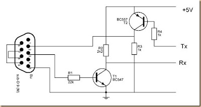
 converter rs232 to arduino circuit diagram

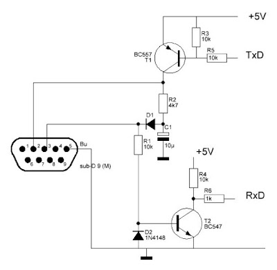
The schema in this article is an RS232 converter, it is possible to connect an Arduino bootloader or your chip with a RS232 port. Here are two versions, one very simple and functional above and one below a little more sophisticated. The port 232 gives a bit more work than USB, but in case of equipment that only have this feature that is a good outlet.

 Converter RS232 to Arduino Circuit Diagram

 converter rs232 to arduino circuit diagram

Read More..

Thursday, August 14, 2014

Simple Ac To Dc Converter Wiring diagram Schematic

This is simple Ac To Dc converter schema diagram. By coupling two back-to-back diodes in series with an ac power schema, a voltage of about 1.4 Vpp can be obtained. This voltage is useful for exciting the primary coil of a small transformer. The voltage induced in the secondary coil can then be rectified and used to power solid-state control diagram. The forward-voltage drop of the diodes is inherently constant and stable over a wide range of ac-schema power variations. 

The resulting voltage developed across the transformer windings is also free from variation that might be caused by changes in the schema`s current or voltage. In the schema, a lamp (LMP-1) is connected to the primary ac input line (Ll and L2) through a pair of inverse-parallel-connected power diodes (Dl and D2). As power flows to the lamp, a drop of about 0.7 V is alternatively developed across each of the diodes. 

This voltage feeds the primary of a small transformer (Tl). T1 can be a small 8- to 500- transistor radio output, etc. This will deliver about 11 Vpp across its secondary winding. LMP1 can be a small 120-V lamp of 5 to 25 W, etc.

Ac To Dc Converter Circuit Diagram

Ac To Dc Converter Circuit Diagram


Simple Ac To Dc Converter Circuit Diagram
Read More..