Friday, December 12, 2014
Plus and Minus DC Power Supply

This is a classic example of a regulated DC power supply that produces both a positive 15v and a negative 15v from a 20vac wall adapter.

Thursday, November 13, 2014
3 30V 3A Adjustable Regulated DC Power Supply
This power supply is meant as an auxiliary or as a permanent power supply for all common circuits based on a stabilized DC voltage between 3 and 30V provided that the consumption does not exceed 3A. Of course this power supply unit can also be used for other purposes. Be replacing the trimmer by a potentiometer, it may even be used as an adjustable power supply unit. A good quality heatsink must be used.
[...]
Parts list:
R1 = 8.2K
R2 = 2.2K
R3 = 680R
R4 = 1K
R5 = 82K
R6 = 0.18R/5W
C1 = 470p
C2 = 100nF-63V
C3 = 100nF-63V
C4 = 100uF-63V
C5 = 10KuF-60V
D1-D6 = 6.6A
Q1 = MJ3001 (Darligton)
IC1 = UA723D
Specifications:
* Overload protected
* Sshort-circuit stable
* Output current: max. 3A
* Output ripple voltage: 0.5mV
* Output voltage: adjustable from 3 to 30V, stabilized
* Input voltage: 9 to 30V AC (depending on the desired output voltage)
Source: http://www.extremecircuits.net/2010/02/3-30v-3a-adjustable-regulated-dc-power.html
13 8V 20A DC Power Supply
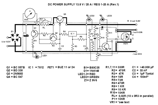
The following DC Power supply circuit is a linear power supply (using transformer). The voltage output of 13.8V power supply is highly regulated, can be adjusted in the moderate range, at up to 20A continuous current. This power supply is suitable for use for amateur radio equipment. DC Power supply is easily constructed and suitable for heavy duty because it is very efficient, small and lightweight.
In the DC power supply presented here, the pass transistors are located in the negative rail and connected in common-emitter configuration rather than as emitter-followers. Thanks to this, the regulator’s minimum voltage drop is extremely low, only about 0.1V for the transistors plus 0.5V for the equalizing resistors.
DC Power Supply Circuit
The other advantage is that the collectors are directly connected to the negative pole of the power supply’s output, which in most applications is grounded. That means that no insulation is required between the transistors and the grounded power supply cabinet! This eases the cooling very considerably. Thanks to the low regulator drop, a low cost 25V filter capacitor can be used.
Some Notes of DC Power Supply Circuit
- Use a transformer for the primary voltage you need. The 3A fuse is for 220 or 240V primaries. If you use something in the neighborhood of 110V, use a 6A fuse.
- The rather high transformer rating of 35A accounts for the losses that occur due to the capacitive input filter. If your transformer is rated for capacitive input, then a 25A value is enough.
- Of course you can make up C1 by placing several smaller capacitors in parallel. Likewise, the 0.1 Ohm, 5 Watt resistors can be made up by several in parallel, for example by 5 resistors of 0.5 Ohm, 1 Watt each.
- The LM336Z-5.0 voltage reference IC should not be replaced by a zener diode. Zeners are not nearly as stable. A different voltage reference IC can of course be used, if R2 and R3 are modified for the different voltage.
- D1 and Q2 through Q6 need heatsinking. Only Q2 needs insulation. D1 dissipates up to 60W, Q2 up to 25W, while the pass transistors dissipate up to 30W each in normal use, but may reach a level of 130W during short circuit! Take this into account when choosing the heat sink!
- R5 exists only to make sure that the transistors can actually be driven off. The 741 is not a single-supply operational amplifier, so it cannot drive its output very low. If a true single-supply opamp is used, then R5 becomes unnecessary.
Tuesday, November 4, 2014
Small DC Motor Control Using PWM
Small DC Motor Control Circuit Diagram :
Sunday, October 5, 2014
Step Up Input Voltage DC DC Converter
Monday, September 8, 2014
DC Converter DC 12V to 24V Wiring diagram Schematic
The coil should be wound on a ferrite core in the form of 1 cm and consists of 100 turns of wire of 1 mm section.
Friday, September 5, 2014
5W 5W AMPLIFIER WITH DC VOLUME CONTROL TDA7496
 |
| 5W+5W AMPLIFIER WITH DC VOLUME CONTROL |
Tuesday, September 2, 2014
DC motor driver with H Bridge IC L293D
0 0 Motor silent
1 0 motor rotates counterclockwise
0 1 Motor berputer clockwise
1 1 Motor silent
Description: Enable Input given a logic 1 to obtain such data in the table above.
Tuesday, August 26, 2014
Simple Variable Dc Supply Step Wiring diagram Schematic
Thursday, August 21, 2014
3000 watt power inverter 12V DC to 230V AC
| Circuit Diagram of 3000 watt power inverter 12V DC to 230V AC |
 |
| Fig. 2: Sine-wave voltage and conventional square wave voltage with both 230 Volt rms |
 |
| Fig. 3: Square wave voltage with duty cycle 25% for 230 Volt rms ("modified sine") |


 |
| fig.: output voltage with no load or inductive load. |
 |
| fig.: resistor 0,001 Ohm made of high-grade steel sheet metal |

 |
| fig.: control electronics on strip hole plate (previous version) and PCB of the "professional edition" |

 |
| fig.: heat sink, mosfet transistors, connections. |

 |
| fig.: 1500 VA inverter with 2 parallel transformers and 1000 VA inverter |
Tuesday, August 19, 2014
1 25V to 25V To DC power supply
This is a DC power supply schema.This schema is based on LM317 Variable Regulator.This Regulator needs at least 28v(DC).Then it will out put 1.25v to 25v DC.So I suppose this would be an important schema for you all.
Note
# 5K ohm Change If you want to change the out put voltage
# This schema supplies 1.3A.
1000 Volt DC to DC Regulator Circuit
The operation of the DC high voltage dc is the same principle as written in previous articles. The difference shown is this scheme is a converter output voltage high and can be arranged.
If a particular transformer mentioned in the scheme is not available, each AC transformer with 117V primary specification, 63V AC CT secondary to work. In this case, operating the converter circuit in a transformer sweet spot, you may need to select a frequency of unity.
Friday, August 15, 2014
1 3V DC to 12 2V DC Regulator Power Supply
In addition, the power supply circuit is also equipped with over-current protection or shield against belebih flow. Power supply circuit is very simple, but the quality is quite good, made her basiskan regulator IC LM723 is a pretty legendary.

Description:
R2 to set the output voltage. The maximum current is determined by R3, over-current protection circuit inside the LM723 to detect the voltage on R3, if it reaches 0.65 V, the voltage output will be off her. So the current through R3 can not exceed 0.65 / R3 although output short-circuit in his.
C3 and C4 are ceramic capacitors, as much as possible directly soldered to the PCB, this is because the LM723 is prone to oscillation that is not cool.
LM723 works with 9.5V input voltage to 40 V DC and the LM723 can generate its own current of 150mA when the output voltage is not more than 6-7V under input voltage.
Specifications:
Output (value estimated):
Vmin = (R4 + R5) / (R5 * 1.3)
Vmax = (7.15 / R5) * (R4 + R5)
Imax = 0.65/R3
Max. Power on R3: 0.42/R3
Min. DC Input Voltage (pin 12 to pin 7): Vmax + 5
Component List:
B1 40V/2.5A
C1 2200uF (3300uF even better)
C2 4.7uF
C3 100nF
C4 1NF
C5 330nF
C6 100uF
Green LED D1
D2 1N4003
F1 0.2A F
F2 2A M
IC1 LM723 (in a DIL14 plastic package)
R1 1k
R2 Pot. 5k
R3 0.56R/2W
R4 3.3k
R5 4.7k
S1 250V/1A
T1 2N3055 on a heatsink 5K / W
TR1 220V/17V/1.5
Thursday, August 14, 2014
Universal DC Power Supply

Simple Micro Inverter circuit DC voltage AC 12v x110v

This schema has the power transistor and that depends on the transformer.

Simple Ac To Dc Converter Wiring diagram Schematic

Simple Ac To Dc Converter Circuit Diagram
