Thursday, November 13, 2014
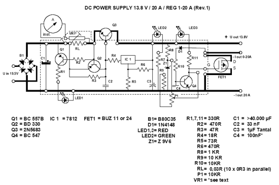
13 8V 20A DC Power Supply
The following DC Power supply circuit is a linear power supply (using transformer). The voltage output of 13.8V power supply is highly regulated, can be adjusted in the moderate range, at up to 20A continuous current. This power supply is suitable for use for amateur radio equipment. DC Power supply is easily constructed and suitable for heavy duty because it is very efficient, small and lightweight.
In the DC power supply presented here, the pass transistors are located in the negative rail and connected in common-emitter configuration rather than as emitter-followers. Thanks to this, the regulator’s minimum voltage drop is extremely low, only about 0.1V for the transistors plus 0.5V for the equalizing resistors.
DC Power Supply Circuit
The other advantage is that the collectors are directly connected to the negative pole of the power supply’s output, which in most applications is grounded. That means that no insulation is required between the transistors and the grounded power supply cabinet! This eases the cooling very considerably. Thanks to the low regulator drop, a low cost 25V filter capacitor can be used.
Some Notes of DC Power Supply Circuit
- Use a transformer for the primary voltage you need. The 3A fuse is for 220 or 240V primaries. If you use something in the neighborhood of 110V, use a 6A fuse.
- The rather high transformer rating of 35A accounts for the losses that occur due to the capacitive input filter. If your transformer is rated for capacitive input, then a 25A value is enough.
- Of course you can make up C1 by placing several smaller capacitors in parallel. Likewise, the 0.1 Ohm, 5 Watt resistors can be made up by several in parallel, for example by 5 resistors of 0.5 Ohm, 1 Watt each.
- The LM336Z-5.0 voltage reference IC should not be replaced by a zener diode. Zeners are not nearly as stable. A different voltage reference IC can of course be used, if R2 and R3 are modified for the different voltage.
- D1 and Q2 through Q6 need heatsinking. Only Q2 needs insulation. D1 dissipates up to 60W, Q2 up to 25W, while the pass transistors dissipate up to 30W each in normal use, but may reach a level of 130W during short circuit! Take this into account when choosing the heat sink!
- R5 exists only to make sure that the transistors can actually be driven off. The 741 is not a single-supply operational amplifier, so it cannot drive its output very low. If a true single-supply opamp is used, then R5 becomes unnecessary.
Monday, August 25, 2014
Symmetric Power Supply Using Transformer
A transformer that reads 12V CT 12, meaning that as they pass rectifier (diode) will produce a voltage 12, 0,-12V and 0 (CT) serves as a ground (neutral phase). If there is no writing can be measured using the AVO meter digital with measuring range AC position.
However transformers can also produce high voltage 24V, that is by connecting the 12V left and right in to rectifier diode without functioning 0 (CT).
In Figure 1, show how to count transformer voltage value 12V &12V.
Place a Black Probe in the center tap; Place a Red probe to left-tap, see scale needle the AVO meter. Next, move red probe to right-tap, see scale needle the AVO meter again. If the same of value then called a symmetric voltage.
| Figure 1 | |
| Power Supply Circuit - Symmetric Power Supply |
And in Figure 2, show how to make a 24V voltage.
further development please try it yourself.
| Figure 2 Symmetric Power Supply |
In Figure 3, show schematic diagram, how to connect the transformer to the rectifier diode will produce a voltage 12V and-12V.
Electrolit capacitors and capacitor serves to dissipate electric corrugation of the magnetic induction in the transformer or eliminate the hum.
| Schematic Diagram Symmetric Power Supply |
Beware, do not touch parts of the primary transformer because it is dangerous.
When do the splicing / soldering unplug the power cord from the outlet of your home.
May be useful.
