Showing posts with label using. Show all posts

Monday, November 17, 2014

Rain Detector using SCR 106CY

Rain Detector using SCR 106CY

This circuit uses a sensor made of a small piece of circuit board and recorded a simple SCR circuit to detect rain and sound of a bell. The SCR could also be used to activate a relay, light a lamp, or send a signal to a security system.

1. The sensor is a small piece of PC board etched to the pattern showen in the schematic. The traces should be very close to each other, but never touching. A large spiral pattern would also work.
2. Make sure to use a loud buzzer.
Read More..

Sunday, November 16, 2014

Car audio amplifier using TDA2003 IC


Easy low power car audio amplifier circuit on TDA 2003. The circuit is Easy to construct. TDA2003 is an integrated radio amplifier from ST Micro electronics that like short circuit protection for all pins, thermal over low harmonic distortion, low cross over distortion etc. In the circuit given here TDA2003 is wired as a mono amplifier operating from a 12V .

Resistors R2 and R3 forms a feedback network that sets the amplifiers gain. C7 input DC de-coupling capacitor and C5 couples the speaker to the amplifiers output. C4 } for improving the ripple rejection C1 and C2 are employed for power filtering. C3 and R1 are used for setting the frequency cut-off. Network comprising of C6 and R4 for frequency stabilization and oscillation.

Notes.

  • Assemble the circuit on a good quality PCB.
  • Heat sinks are necessary for both ICs.
  • The circuit can be operated from 12V DC.
  • S1 is the ON/OFF switch.
Read More..

Saturday, November 15, 2014

FLASHER CIRCUIT USING NE 555

Flashing circuits are very interesting. They grab your attention and can be used in many applications. They consume very little energy and a single cell can last as long as 12 months. You can flash globes, LEDs and pulse all types of devices such as motors, solenoids and piezo diaphragms. In this discussion we will cover a number of interesting "oscillator circuits." They can be adapted for other applications - but to do this you have to know how they work. This is not easy as most of them are quite complex. In fact oscillator circuits are one of the most difficult circuits to understand. But if you read the text, everything will become clear.

Circuit Description


This is the circuit diagram of lamp flasher operated from mains. By this you can flash up to 200 Watt lamps at rates determined by you. IC NE555 is wired as an astable multivibrator for producing the pulses for flashing the lamp. The flashing rate can be set by the value of resistors R2 & R3.

Diodes D1 & D2 provides a half wave rectified regulated supply for the IC. Transistor T1 is used to drive triac and triac BT136 for driving the load. Resistor R4 limits the base current of Q1.

Flashing Circuit Diagram & Parts List


Notes

  • Assemble the circuit on a good quality PCB or common board.
  • Connect a 100K pot instead of R2 if you need frequent changes in rate.
  • Many parts of the circuit are live with potential shock hazards. So please be careful.
  • As usual use an IC holder for mounting the IC.
Read More..

Friday, November 14, 2014

LINE FOLLOWER ROBOT USING 8051

Line follower robots were one of the earliest automatic guided robots. They are able to follow a line marked on a contrasting background, usually a black line on a white surface or a white line on a black surface.  Usually the line follower robot works on a closed loop feedback algorithm where the feedback from the line sensor is used by the controller for correcting the path of the robot. The sensors are usually LED/LDR, LED/Photodiode or LED/Phototransistor pairs and the controller is an electronic circuit which executes the desired feedback algorithm. Gear motors are used for driving the robotic wheels.

The line follower robot presented here is designed to follow a black line on a white background. It has a pair of sensors (LED / LDR)  and works on a simple “align robot on center of the line algorithm”. Actually you does not need a microcontroller for implementing such a simple robot. A set of comparators and a motor driver circuit will happily do the job. But I am using the microcontroller  just to demonstrate the technology. Also this project serves as a platform for advanced line follower robots which works on complex algorithms. AT89S52 from Atmel is the microcontroller used here.

Sensor

The sensor part consists of a set of  LED /  LDR pairs  for the left side and right sides. These LED / LDR pairs detect the black line on the white surface on which the robot is supposed to roam. The LDR has an inverse relationship between its resistance and the light falling on it. When a particular LED / LDR pair is above  the white surface  the reflected light falls on the LDR and its resistance drops, conversely when the LED / LDR pair is above  the black  line, its resistance rises.  This variation in resistance of the LDRs are used to asses the orientation of the line follower robot in the X-Y plane. The figure shown below depicts the sensor circuit.


In the circuit, resistors R1 and R2 limits the current through the illuminating LEDs D1 and D2. Resistors R3, R5 and R6, R8 forms a voltage divider network together with the corresponding LDRs. The output of the sensor circuit is taken from the points labelled A and B in the circuit diagram.The table below shows the voltage at nodes A and B for the possible orientations of the sensor module.


Comparator Circuit

The job of the comparator circuit is to convert analog voltage output of the sensor into a digital format for the microcontroller to read. The comparator circuit is built around opamp IC  LM324 (IC1). LM324 is a general purpose quad opamp which can be operated from a single supply. Out of the four comparators inside LM324, only two are used here. One for the left side and the other for the right side. Circuit diagram of the comparator section is shown in the figure below.


Preset resistor R10 and R11 are used to set the 1V reference  for the left and right comparators respectively. Output from the left and right sensors (node A and B) are connected to the non inverting input on the left and right comparators. Output of the left comparator is connected to P1.o of the microcontroller and output of the right comparator is connected to P1.1 of the microcontroller. Both comparators are wired in non inverting mode and the table given below shows their output  voltage with respect to the possible input voltage combinations.


Microcontroller (AT89S52)

The task of the microcontroller here is to control the left and right motors according to the feedback signals from the left and right comparators so that the robot remains on the correct path (the black line). The logic executed by the microcontroller for keeping the robot in track is illustrated in the table below.


Motor Driver Circuit

The job of the motor driver circuit  is to drive the motors according to the output signals from the microcontroller. The motor driver circuit is based on ULN2003A IC. ULN2003A is a high current (500mA), high voltage (50V) darlington array consisting of seven darlington pairs with common emitter and open collector. Out of the seven channels available in the IC,only two are used here. One for the left channel and one for the right channel. Schematic of the motor driver circuit is shown in the figure below. The operation of  ULN2003 is very simple to explain. When a particular input line (say pin 1) is made high the corresponding output line (pin 16 goes low) and vice versa.


Capacitors C4 and C5  isolates the remaining parts of the circuit from the electric interference produced by the motor. The back emf voltage produced when  motor is switched and the voltage spikes due to arcing of brushes mainly accounts for the above said electrical interference. These capacitors are very essential and without them you can expect sudden crashes from the microcontroller side.

Complete Circuit Diagram


Switch S1, capacitor C3 and resistor R9 forms a debouncing reset circuit for the microcontroller. Capacitors C1, C2 and 12MHz crystal X1 are associated with the microcontroller’s clock circuit. R12 and R13 are pull-up resistors. Remaining sections of the circuit were explained already.

Program

ORG 000H                 // origin
MOV P1,#00000011B        // sets port 1 as input port
MOV P0,#00000000B        // sets port 0 as output port
BACK : MOV P0,#00000011B  // starts both motors
       JB P1.0, LABEL1 // branches to LABEL1 if left sensor is ON
       CLR P0.0           // stops left motor
       SETB P0.1          // runs right motor
       ACALL WAIT1        // calls WAIT1 subroutine
       SJMP BACK          // jumps back to the BACK loop
LABEL1 : JB P1.1, LABEL2 // branches to LABEL2 if right sensor is ON
         SETB P0.0         // runs left motor
         CLR P0.1          // stops right motor
         ACALL WAIT2       // calls WAIT2 subroutine
         SJMP BACK         // jumps back to the BACK loop
LABEL2 : SJMP BACK         // jumps back to the BACK loop
WAIT1 : JNB P1.0,WAIT1 // waits until robot is back from rightward deviation
         RET              // returns from WAIT1 subroutine
WAIT2 : JNB P1.1,WAIT2 // waits until robot is back from leftward deviation
        RET                 // returns from WAIT2 subroutine
END                       // end statement

About the Program

The first part of the program initializes Port 1 as input port and Port 0 as output part. After this,  both motors are started so that the robot goes straight. Then the programs checks whether there is a deviation to right. If there is a deviation to right, the program stops left motor and runs right motor and waits until the robot comes back from the deviation. When the robot is back on line again, both motors are started.
If there is no deviation to right, the program checks for a deviation to left. If there is a deviation to left, left motor is stopped and right motor is activated. This condition is maintained until the robot is back on track. When the robot is back on track again, both motors are started. Lastly if there is no deviation to left or right, both motors are kept ON.

Notes

  • A 6V battery can be used for powering the circuit even though  the power supply shown in the circuit diagram is 5V DC.
  • For setting up the robot, place the robot on the line so that both the sensor pairs point on white and the black line goes in between them. Then adjust preset resistors R10 and R11 so that the LEDs D3 and D4 glows.
  • Sensor LEDs D1 and D2 are  ultra-bright green LEDs.
  • OPAMP output LEDs D3 and D4 are general purpose, miniature, yellow LEDs.
  • Sensor LDRs R4 and R7 are general purpose LDRs.
Read More..

Thursday, November 13, 2014

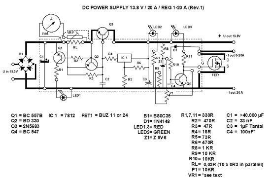
13 8V 20A DC Power Supply
https://blogger.googleusercontent.com/img/b/R29vZ2xl/AVvXsEhhQ-XWj6uGtL5nJkE_aft47HENOqaieTBF9xTgo8_o1aRDFWPY-5Lvd0n-zpvAvqaPxpELH0a7mzMTU-jvMEorZ1RkRrD1un79kqEuFbO9oB6FKrUenR3Rp1cnpdcTNJJh3KubhV0hJenX/s1600/13.8V+20A+power+supply.gif

The following DC Power supply circuit is a linear power supply (using transformer). The voltage output of 13.8V power supply is highly regulated, can be adjusted in the moderate range, at up to 20A continuous current. This power supply is suitable for use for amateur radio equipment. DC Power supply is easily constructed and suitable for heavy duty because it is very efficient, small and lightweight.

In the DC power supply presented here, the pass transistors are located in the negative rail and connected in common-emitter configuration rather than as emitter-followers. Thanks to this, the regulator’s minimum voltage drop is extremely low, only about 0.1V for the transistors plus 0.5V for the equalizing resistors.

DC

DC Power Supply Circuit

The other advantage is that the collectors are directly connected to the negative pole of the power supply’s output, which in most applications is grounded. That means that no insulation is required between the transistors and the grounded power supply cabinet! This eases the cooling very considerably. Thanks to the low regulator drop, a low cost 25V filter capacitor can be used.

Some Notes of DC Power Supply Circuit

  • Use a transformer for the primary voltage you need. The 3A fuse is for 220 or 240V primaries. If you use something in the neighborhood of 110V, use a 6A fuse.
  • The rather high transformer rating of 35A accounts for the losses that occur due to the capacitive input filter. If your transformer is rated for capacitive input, then a 25A value is enough.
  • Of course you can make up C1 by placing several smaller capacitors in parallel. Likewise, the 0.1 Ohm, 5 Watt resistors can be made up by several in parallel, for example by 5 resistors of 0.5 Ohm, 1 Watt each.
  • The LM336Z-5.0 voltage reference IC should not be replaced by a zener diode. Zeners are not nearly as stable. A different voltage reference IC can of course be used, if R2 and R3 are modified for the different voltage.
  • D1 and Q2 through Q6 need heatsinking. Only Q2 needs insulation. D1 dissipates up to 60W, Q2 up to 25W, while the pass transistors dissipate up to 30W each in normal use, but may reach a level of 130W during short circuit! Take this into account when choosing the heat sink!
  • R5 exists only to make sure that the transistors can actually be driven off. The 741 is not a single-supply operational amplifier, so it cannot drive its output very low. If a true single-supply opamp is used, then R5 becomes unnecessary.
Read More..

Tuesday, November 4, 2014

Small DC Motor Control Using PWM

Small DC motors are efficiently controlled using pulse-width modulation (PWM) method. The circuit described here is built around an LM324 low-power quad-operational amplifier. Of the four op-amps (operational amplifiers) available in this IC, two are used for triangular wave generator and one for comparator. Op-amp N2 generates a 1.6kHz square wave, while op-amp N1 is configured as an integrator. The square wave output of N2 at its pin 14 is fed to the inverting input (pin 2) of N1 through resistor R1. As N1 is configured as an integrator, it outputs a triangular wave of the same frequency as the square wave. The triangular wave is fed to pin 5 of op-amp N3, which is configured as a comparator.

Small DC Motor Control Circuit Diagram :

Motor

The reference voltage at pin 6 of the comparator is fixed through the potential divider arrangement formed by potmeter VR1 and resistors R4 and R5. It can be set from –6V (lowermost position of VR1) to +6V (uppermost position of VR1). 
  
The triangular wave applied at pin 5 of N3 is compared with the reference voltage at its pin 6. The output at pin 7 is about +12V when the voltage at pin 5 is greater than the voltage at pin 6. Similarly, the output at pin 7 is about -12V when the voltage at pin 5 is lower than the voltage at pin 6.

The output from comparator N3 is the gate voltage for n-channel MOSFET (T1). T1 switches on when the gate voltage is positive and switches off when the gate voltage is negative. Setting of the reference voltage therefore controls the pulse-width of the motor. When T1 is switched on for a longer period, the pulse width will be wider, which means more average DC component and faster speed of the motor. Speed will be low when the pulse width is small. Thus potmeter VR1 controls the speed of the motor.

Assemble the circuit on a general-purpose PCB and enclose in a suitable cabinet. The circuit requires ±12V power supply for its working. It can also be modified to control the speed of a 6V or 24V DC motor.


Read More..

Sunday, November 2, 2014

BURGLAR ALARM USING IC TIMER 555 556 ELECTRONIC DIAGRAM


BURGLAR ALARM USING IC TIMER 555/556 ELECTRONIC DIAGRAM

circuit diagram of burglar alarm using IC timer 555/556 is functioned as an alarm to prevent thief entering your house. The alarm would produce loud sound when a thin wire connecting resistor R1 with IC pin no 4 is broken. Thin fiber is used as the wire. The thinner the wire, the more responsive the alarm. This circuit needs 5-15V power supply, buzzer is used as a speaker. Here is the circuit schematic :

Parts list :
  •     Resistor R1 : 10k
  •     Resistor R2 : 68k
  •     Resistor R3 : 1k
  •     Polar capacitor C1 : 1uF/15 B
  •     Capacitor C2-C3 : 0.01uF
  •     IC Timer : NE555
Read More..

Sunday, October 5, 2014

Sport Analyzer Using an Accelerometer overview and explanation


Overview

This sport accelerometer uses a transmitter with accelerometer that reads data and transmits to a computer with DSP while being used in athletics to determine the wrong foot steps as the athletes run.

Explanation

The development of the device includes all the holes which contain the programming header called ICD located above the power label which has the serial lines and above the ON/OFF switch for the external power. These headers serve the purpose of providing backup by plugging wires in the event of lost wireless connection due to low battery. Other components used are the low dropout voltage regulator (LDO), lithium battery charger, Xbee, and the accelerometer. A Digital Signal Processing (DSP) was implemented in order to recognized sounds as the logging starts on a whistle blow.

The result of the two layer lip was due to the location of the lithium battery under the PCB. On order to get proper data for plotting, a gyro should be added to provide help after the accelerometer was attached. The use of Xbee module may not be necessary and other alternatives can made. A simple 868 MHz radio transceiver can be used to provide communication.

Read More..

Saturday, October 4, 2014

Radio Remote Control using DTMF

RadioRadio Remote Control using DTMF Schematic

Here is a circuit of a remote control unit which makes use of the radio abundance signals to ascendancy assorted electrical appliances. This alien ascendancy assemblage has 4 channels which can be calmly continued to 12. This ambit differs from agnate circuits in appearance of its artlessness and a absolutely altered abstraction of breeding the ascendancy signals. Usually alien ascendancy circuits accomplish use of bittersweet ablaze to address ascendancy signals. Their use is appropriately bound to a actual bedfast breadth and line-of-sight. However, this ambit makes use of radio abundance to address the ascendancy signals and appropriately it can be acclimated for ascendancy from about anywhere in the house.

Here we accomplish use of DTMF (dual-tone multi frequency) signals (used in telephones to punch the digits) as the ascendancy codes. The DTMF tones are acclimated for abundance accentuation of the carrier. At the receiver unit, these abundance articulate signals are intercepted to access DTMF tones at the apostle terminals. This DTMF arresting is affiliated to a DTMF-to-BCD advocate whose BCD achievement is acclimated to switch-on and switch-off assorted electrical appliances.

Read More..

Electronic Combination Lock using LS7220

Electronic
This circuit diagram could be a simple electronic combination lock using LS 7220. Rangkaian Kunci Digital Ber-password Password Digital is used to activate a relay for controlling (on & off) any device when a preset combination of four digits are pressed.The circuit is operated from 5V to 12V.

To set the mix connect the acceptable switches to pin 3,4,5 and vi of the IC through the header.As an example if S1 is connected to pin 3, S2 to pin four , S3 to pin 5, S4 to pin vi of the IC ,the combination are 1234.This way we can produce any four digit combos.Then connect the remainder of the switches to pin two of IC.This will cause the IC to reset if any invalid secrets pressed , and entire key code must be re entered.

When the correct key combination is pressed the out put ( relay) are activated for a preset time determined by the capacitor C1.Here its set to be 6S.Increase C1 to increase on time.

For the key pad, prepare switches in a 3X4 matrix on a PCB.Write the digits on the keys using a marker.Instead of using numbers I wrote some symbols!.The unhealthy guys are a lot of confused by this.

List komponen Electronic Combination Lock
  • C1 1uF/25Vr
  • C2 220uF/25V
  • R1 2.2K
  • Q1 2N3904 NPN Transistor 2N2222
  • D1 1N4148 Rectifier Diode
  • K1 12V SPDT Relay, Any appropriate relay with 12V coil
  • U1 LS7220 Digital Lock IC
  • S1-S12 PST Momentary Pushbutton
  • HD1 12 Position Header
Read More..

Sunday, September 14, 2014

Long Duration Timer using A Ttiny 2313

This timer schema is designed to switch on a 12 V load in a solar-powered installation for a preset period at the press of a button. When the period has expired a latching relay disconnects both the load and the controller schema from the 12 V supply. The length of the period can be configured by making suitable changes to the microcontroller’s source code.


Software

When button S1 is pressed a voltage appears across relay coil L1, and the relay switches the load on. Since the relay is a latching type, it remains in this state when the but ton is released. There is now a supply to the 78L05 voltage regulator (a low-dropout type such as the LP2950CZ-5.0 may also be used) and the microcontroller is powered up. In the microcontroller the timer program runs until the configured time interval has elapsed. Around 90 % of the way through the time period LED D2 lights as a warning that the load will shortly be switched off, and this time can also of course be configured by changing the software.

When the full time interval has elapsed the microcontroller sets an output (pin 7) high, which triggers the CNY 17-3 optocoupler and in turn drives relay coil L2. The relay returns to its initial state, disconnecting the load as well as the controller (which is also powered via the relay contact) from the 12 V supply.

Long Duration Timer Circuit Diagram

Long

The author used a miniature 16 -by-2 LCD panel type HMC16223SG in his prototype, measuring just 52 mm by 20 mm. It is of course possible to use any standard LCD module that uses an HD44780-compatible controller. Note that P1 is used to adjust the contrast of the LCD: if the display appears blank it is worth checking the contrast set-ting before suspecting a more serious problem! If desired, the LCD can be dispensed with, along with the corresponding parts of the source code.

The upper line of the LCD shows the total time period, in seconds, for which the soft-ware is configured, while the lower line shows the time, in seconds, since the button was pressed.

The Lcddump shows the LCD settings under BASCOM-AVR. The source code for the program is available for download. Link
Read More..

Saturday, September 13, 2014

Morning Alarm Wiring diagram Schematic Using LDR

Morning


Description

 Circuit showing a morning alarm.Here we have used a switching transistor.When the sun rise up ldr is low resistance so the ldr is conduct and a positive volt coming to the base of the Q1 there for the transistor will switch.This time  the buzzer is ON . Adjust the preset control the intensity of light.Manually cut off the power.Are you interested please comment and join this site


Component Required

                Resistor  4.7k preset  , LDR

                Transistor   BC 548

                Buzzer


Read More..

Monday, September 8, 2014

Battery Discharger Using Discrete Components

The battery discharger published in this website may be improved by adding a Schottky diode (D3). This ensures that a NiCd cell is discharged not to 0.6–0.7 V, but to just under 1 V as recommended by the manufacturers. An additional effect is then that light-emitting diode D2 flashes when the battery connected to the terminals is flat. The schema in the diagram is based on an astable multivibrator operating at a frequency of about 25 kHz. When transistor T2 conducts, a current flows through inductor L1, whereupon energy is stored in the resulting electromagnetic field. When T2 is cut off, the field collapses, whereupon a counter-emf is produced at a level that exceeds the forward voltage (about 1.6 V) of D2.

Battery

A current then flows through the diode so that this lights. Diode D1 prevents the current flowing through R4 and C2. This process is halted only when the battery voltage no longer provides a sufficient base potential for the transistors. In the original schema, this happened at about 0.65 V. The addition of the forward bias of D3 (about 0.3 V), the final discharge voltage of the battery is raised to 0.9–1.0 V. Additional resistors R5 and R6 ensure that sufficient current flows through D3. When the battery is discharged to the recommended level, it must be removed from the discharger since, in contrast to the original schema, a small current continues to flow through D3, R2-R3, and R5-R6 until the battery is totally discharged.

The flashing of D2 when the battery is nearing recommended discharge is caused by the increasing internal resistance of the battery lowering the terminal voltage to below the threshold level. If no current flows, the internal resistance is of no consequence since the terminal voltage rises to the threshold voltage by taking some energy from the battery. When the discharge is complete to the recommended level, the LED goes out. It should therefore be noted that the battery is discharged sufficiently when the LED begins to flash.
Read More..

Monday, August 25, 2014

Symmetric Power Supply Using Transformer

Symmetric Power Supply is the power supply that uses a transformer with dual voltage. In this power supply will generate 3 phase voltage is positive (), negative (-) and CT (0). CT = Center Tap).
A transformer that reads 12V CT 12, meaning that as they pass rectifier (diode) will produce a voltage 12, 0,-12V and 0 (CT) serves as a ground (neutral phase). If there is no writing can be measured using the AVO meter digital with measuring range AC position. 
Black probe in the middle and the red probe to look left and right voltage tap on the secondary. If same value between tap the left and right, this is called symmetric transformers.
However transformers can also produce high voltage 24V, that is by connecting the 12V left and right in to rectifier diode without functioning 0 (CT).
Now, Power Supply Symmetric widely used in Power Amplifier., The power of the power amplifier weighs around 20-40kg, as it uses a large ampere transformer and cooling system uses aluminum(HEAT SINK).


In Figure 1, show how to count transformer voltage value 12V &12V.
Place a Black Probe in the center tap; Place a Red probe to left-tap, see scale needle the AVO meter.  Next, move red probe to right-tap, see scale needle the AVO meter again. If the same of value then called a symmetric voltage.
Power
Figure 1
Power Supply Circuit - Symmetric Power Supply


And in Figure 2, show how to make a 24V voltage.
further development please try it yourself.
Power
Figure 2
Symmetric Power Supply


In Figure 3, show schematic diagram, how to connect the transformer to the rectifier diode will produce a voltage 12V and-12V.
Electrolit capacitors and capacitor serves to dissipate electric corrugation of the magnetic induction in the transformer or eliminate the hum.

Power
Schematic Diagram
Symmetric Power Supply

Beware, do not touch parts of the primary transformer because it is dangerous.
When do the splicing / soldering unplug the power cord from the outlet of your home.

May be useful.
Read More..

Friday, August 22, 2014

1 Watt Tiny Audio Amplifier Using LM386

Tiny Audio Amplifier Using LM386
Specifications
The Tiny Audio Amplifier kit is a good choice for battery operation. It is based on LM386 IC.
  • Power supply - 6 - 12 VDC
  • Output power - 1 W, 8 Ohm
  • The quiescent power drain is only 24 mW when operating from 6 VDC
  • Self-centering output quiescent voltage
  • Onboard PRESET to adjust volume
  • Terminal pins for connecting power supply, audio signal and speaker

  • Power-On LED indicator
  • ON/OFF PCB mounted slide switch for power supply
  • Four mounting holes of 3.2 mm each
  • PCB dimensions 44 mm x 44 mm
Schematic

1

Inputs - Outputs configuration
Inputs
 Parts List
 PCB
Read More..