Friday, December 12, 2014
Plus and Minus DC Power Supply

This is a classic example of a regulated DC power supply that produces both a positive 15v and a negative 15v from a 20vac wall adapter.

Solar Battery Charger Circuit Schematic
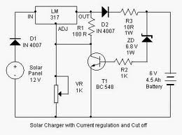
Here is a solar charger circuit that is used to charge Lead Acid or Ni-Cd batteries using the solar energy power. The circuit harvests solar energy to charge a 6 volt 4.5 Ah rechargeable battery for various applications. The charger has Voltage and Current regulation and Over voltage cut off facilities.
Power Amplifier
300w Sub-woofer Power Amplifier - High power amps are not too common as projects, since they are by their nature normally difficult to build and are expensive.
LM3886 Power Amplifier - The LM3886 is a high-performance audio power amplifier capable of delivering 68W of continuous average power to a 4 ohm load and 38W into 8 ohm load.
2.3 GHz Power Amplifier - 2 schematic which contains prototype and real one.
20 Watt Class-A Power Amplifier - This amp uses the basic circuitry of the 60W power amp but has been modified for true Class-A operation.
20 Watt / Channel Stereo Power Amplifier - This project is based almost directly on the typical application circuit in the National Semiconductor specification sheet.
Simple Audio Power Amp - This simple audio power amplifier was originally designed for a circuit board workshop conducted by the OSU IEEE Student Group.
Death of Zen (DoZ) - A New Class-A Power Amp - This project design specifically for headphones.
Simple Current Feedback Power Amplifier - The first version of the amp uses a single power supply and capacitor coupled speaker.
Single Chip 50 Watt / 8 Ohm Power Amplifier - This project is based almost directly on the typical application circuit in the National Semiconductor specification sheet.
Soft-Start Circuit For Power Amps - The circuit presented in the website is designed to limit inrush current to a safe value.
170W Audio Power Amplifier - Suitable for self-powered speakers, sub-woofers and quality car boosters.
Read More..
LM3886 Power Amplifier - The LM3886 is a high-performance audio power amplifier capable of delivering 68W of continuous average power to a 4 ohm load and 38W into 8 ohm load.
2.3 GHz Power Amplifier - 2 schematic which contains prototype and real one.
20 Watt Class-A Power Amplifier - This amp uses the basic circuitry of the 60W power amp but has been modified for true Class-A operation.
20 Watt / Channel Stereo Power Amplifier - This project is based almost directly on the typical application circuit in the National Semiconductor specification sheet.
Simple Audio Power Amp - This simple audio power amplifier was originally designed for a circuit board workshop conducted by the OSU IEEE Student Group.
Death of Zen (DoZ) - A New Class-A Power Amp - This project design specifically for headphones.
Simple Current Feedback Power Amplifier - The first version of the amp uses a single power supply and capacitor coupled speaker.
Single Chip 50 Watt / 8 Ohm Power Amplifier - This project is based almost directly on the typical application circuit in the National Semiconductor specification sheet.
Soft-Start Circuit For Power Amps - The circuit presented in the website is designed to limit inrush current to a safe value.
170W Audio Power Amplifier - Suitable for self-powered speakers, sub-woofers and quality car boosters.
Mini Subwoofer Circuit 22W

The subwoofer is a subwoofer or a speaker to reproduce low frequencies, devotee of 20 Hz to 150 Hz electronic circuit diagram below shows the details of a scheme of the main amplifier TDA1516 22 watt in 4 ohm car subwoofer driver. This device is designed for an existing stereo amplifier, often requires adding another blow to the music of driving a subwoofer.
Thursday, December 11, 2014
VHF Antenna Amplifier

A very simple antenna amplifier electronic circuit project can be designed using this circuit diagram.This antenna amplifier electronic circuit can be used for a frequency range between 1 and 300MHz.
This circuit antenna amplifier can be used for high frequency and VHF band ( for radio and TV) and will provide a 22 dB gain .This antenna amplifier electronic project has a very low noise , under 1.6dB .This VHF, FM amplifier circuit is constructed based on the BFT66 transistor connected in common emitter connection.
Thursday, November 20, 2014
A 4 Digit Keypad Controller Switch Circuit
This is a universal version of the Four-Digit Alarm Keypad . I have modified the design to free up the relay contacts. This allows the circuit to operate as a general-purpose switch. It also means that it can be used to control all of my Alarm Circuits. Ive used a SPCO/SPDT relay - but you can use a multi-pole relay if you wish.
The relay is energized by pressing a single key. Choose the key you want to use - and connect it to terminal "E". Choose the four keys you want to use to de-energize the relay - and connect them to "A B C & D". Wire the common to R1 and all the remaining keys to "F".
The Circuit is easy to use. When you press "E" - current through D2 & R9 turns Q6 on - and energizes the relay. The two transistors - Q5 & Q6 - form a "Complementary Latch". So - when you release the key - the relay will remain energized.
To de-energize the relay - you need to press keys "A B C & D" in the right order. When you do so - pin 10 of the IC goes high - and it turns Q4 on through R8. Q4 connects the base of Q6 to ground. This unlatches the complementary pair - and the relay drops out.
Any keys not wired to "A B C D & E" are connected to the base of Q3 by R7. Whenever one of these "Wrong" keys is pressed - Q3 takes pin 1 low and the code entry sequence fails. If "C" or "D" is pressed out of sequence - Q1 or Q2 will also take pin 1 low - with the same result. If you make a mistake while entering the code - simply start again.
The Keypad must be the kind with a common terminal and a separate connection for each key. On a 12-key pad, look for 13 terminals. The matrix type with 7 or 8 terminals will NOT do. With a 12-key pad - over 10 000 different codes are available. If you need a more secure code - use a bigger keypad with more "Wrong" keys wired to "F". A 16-key pad gives over 40 000 different codes.
The relay is energized by pressing a single key. Choose the key you want to use - and connect it to terminal "E". Choose the four keys you want to use to de-energize the relay - and connect them to "A B C & D". Wire the common to R1 and all the remaining keys to "F".
The Circuit is easy to use. When you press "E" - current through D2 & R9 turns Q6 on - and energizes the relay. The two transistors - Q5 & Q6 - form a "Complementary Latch". So - when you release the key - the relay will remain energized.
To de-energize the relay - you need to press keys "A B C & D" in the right order. When you do so - pin 10 of the IC goes high - and it turns Q4 on through R8. Q4 connects the base of Q6 to ground. This unlatches the complementary pair - and the relay drops out.
Any keys not wired to "A B C D & E" are connected to the base of Q3 by R7. Whenever one of these "Wrong" keys is pressed - Q3 takes pin 1 low and the code entry sequence fails. If "C" or "D" is pressed out of sequence - Q1 or Q2 will also take pin 1 low - with the same result. If you make a mistake while entering the code - simply start again.
The Keypad must be the kind with a common terminal and a separate connection for each key. On a 12-key pad, look for 13 terminals. The matrix type with 7 or 8 terminals will NOT do. With a 12-key pad - over 10 000 different codes are available. If you need a more secure code - use a bigger keypad with more "Wrong" keys wired to "F". A 16-key pad gives over 40 000 different codes.
Interface Relay with PNP transistor
One technique relay drivers from the microcontroller or computer can be made with the driver PNP transistors like the article "Interface Relays With PNP Transistor" ini.This circuit interface is simple and easily applied to a microcontroller or computer parallel port. Interface Relays With PNP Transistor uses 2 transistors 2N3904 and 2n2905/2N2907 UAH as a power relay drivers. The advantages of this circuit can menggeran relay with considerable power with TTL logic input from the computer and microcontroller. Source voltage required to follow the relay circuit is used, for example using a 12V relay, the source voltage to 12V or 24V relays the 24V voltage source. Detailed relay interface circuit and microcontroller or computer can be seen in the following figure.

Function diodes mounted parallel with the relay to prevent backflow into the transistor due to magnetic induction of the relay coil, therefore these diodes must be installed. For installation with a microcontroller or computer which need to be noticed is the Grund computer or microcontroller circuit must be connected to ground in series Interface Relays With this PNP transistors.
Subscribe to:
Posts (Atom)
