Showing posts with label led. Show all posts

Tuesday, November 18, 2014

Running LED with 4017

Running LED with 4017 complete with PCB layout. The series of 8 LED current is the basis for creating an 8-point LED. Slightly different from the running LED with IC 4017 (decade counter), 8 running this led is lit in sequence, but that has been previously flame does not die when the led is lit afterwards. 8 led to death after led to the fire-8. Meanwhile in the running LED (decade counter), the system LED lights like "point", there is only one LED that flashes between the tenth led.

Running

The main component is the IC 74LS164 (SHIFT REGISTER), with its timer is astable multivibrator circuit (using IC NE555).

The series will be more efficient when using a stable power supply (regulator) using IC Regulator 7805. Under this scheme a series of stable power supply 5 volts dc.

rangkaian
Read More..

Thursday, October 30, 2014

0 3 to 1 5V LED Flashlight Circuit Diagram


Its a little wisp of a circuit that allows you to drive a blue or white LED from a low voltage. Normally, if you want to light up a blue or white LED you need to provide it with 3 - 3.5 V, like from a 3 V lithium coin cell. But a 1.5 V battery like a AA cell simply will not work. But using the Joule Thief, it works like a charm. Not only does it work with a brand new battery, but it works until the battery is nearly dead-- down to 0.3 V. Thats well below the point where your other toys will tell you the battery is dead, so it can steal every last joule of energy from the battery (hence the name). To learn how to make one, watch the video, which is available in a variety of formats.

0.3 to 1.5V LED Flashlight Circuit Diagram


Read More..

Tuesday, October 28, 2014

Circuit 3 LED battery monitor

This is the circuit diagram of a 3 LED bar graph type battery monitor circuit that is ideal for monitoring the voltage level of an automobile battery.When battery voltage is 11.5V or less transistor Q1 will be On and the LED D1 will be glowing.When battery voltage is between 11.5 and 13.5V, the transistor Q2 will be On and the LED D2 will be glowing.When battery voltage is above 13.5V the transistor Q3 will be On and the LED D7 will be glowing.

Circuit diagram with Parts list.

Notes.
Assemble the circuit on a general purpose PCB.The battery to be monitored can be connected between the terminals namely A and B.It is always better to use LEDs of different colour.

Read More..

Friday, October 17, 2014

1 5 volt dual LED flasher

This 1.5 volt led fasher runs more than a year on a single d" cell and alternately flashes 2 LEDs at about a 1 second rate. The circuit employs a 74HC14 CMOS hex inverter that will operate at very low voltages (less than 1 volt). One section is used as a squarewave oscillator (pins 1 and 2), while the others are wired to produce a short 10mS pulse on alternate edges of the square wave so the LEDs will alternate back and forth. The output sections each use a capacitor charge pump to increase the voltage for the LEDs. The circuit draws an average current of 800uA from the D battery and the LED peak current is about 40mA with a fresh battery and drops to about 10mA as the battery voltage falls to 1.1 volts. The capacity of a alkaline D cell is about 12 amp hours with a cutoff voltage of 1.1 so the circuit should run about 12/.0008 = 15000 hours or maybe 625 days, but I havent verified that yet. The idea for this circuit came from a single 1.5 volt LED flasher by Dave Johnson that can viewed at


Author : Bill Bowden 
Read More..

Wednesday, October 15, 2014

Build a 10 LED Bar Dot VU Meter Circuit based LM3915

Build a 10 LED Bar Dot VU meter circuit based LM3915. It differs in many respects from other applications on the same chip. The circuit is intended for those who want a VU meter that is connected directly to the output of an power amplifier.

 10 LED Bar Dot VU Meter Circuit based LM3915 Circuit Diagram


It’s possible to adjust the sensitivity to work with amplifiers that have different output power, you just need to change the value of R1 according to Table 1. In case you did’n find the exact resistor value, then choose the next standard value (for example if you cannot find 33K ohm, then find the 36K ohm), or if you want maximum accuracy you need to put resistors in series or in parallel to achieve the correct value.

 
You can use various types of LEDs (round or square) to get the visual and aesthetic result you want. The switch S1 will allow you to choose whether VU meter will work as a bar or one by one (dot). In position ON [closed switch], the LED operation is Bar, while in position OFF [open switch], the LED operate in Dot. In Bar mode, the power consumption rises because all of the LED will be work and can reach up to 150mA.

For amplifier with two channels is obvious that we should build two identical circuits, one for each channel. The operating voltage of the circuit is +12 V. Taking this trend should be done by the tendency of the amp. Usually amps work with voltages which higher than +12 Volts for the circuit. For this reason, we must added a component which can decrease, regulate and stabilize the +Vp voltage at +12 Volts. The component we are used is IC2 (LM317) which is an adjustable voltage regulator and stabilizer.

Using a small brushing is necessary because the differences in the potential entry; output is large so that we develop high levels of temperature. The use of R5 helps in voltage drop to descend the voltage at the input of IC2 at lower levels. The calculation of this resistance is more empirically using Ohm’s law. The voltage at the input of IC2 must be higher than +16 Volts. For example, if the voltage of the amplifier is +50 Volts, we should have a voltage drop 50-16 = 34 Volts on the resistance R5. For the electric current, 50mA average is needed by the circuit [may be up to 150mA], the value of R5 = V / I = 34/0.05 = 680 ohms 2W. You may need to increase or decrease this value by trials. Because the resistor is going to heat up, then it will be better to put some distance from the PCB.

It will be better to set up and measure the output vltage of the IC2 by adjusting TR1 first, you need yo remove IC1 to secure the IC1. If you are able to supply the stabilized +12 V from somewhere in the amplifier circuit, then you’ll need to remove the R5, the IC2 and materials inside the dotted line.

PCB layout design:

PCB

Read More..

Thursday, September 18, 2014

Two Cell LED Torch

It sometimes comes as a bit of a shock the first time you need to replace the batteries in an LED torch and find that they are not the usual supermarket grade alkaline batteries but in fact expensive Lithium cells. The torch may have been a give away at an advertising promo but now you discover that the cost of a replacement battery is more than the torch is worth. Before you consign the torch to the waste bin take a look at this circuit. It uses a classic two-transistor astable multivibrator configuration to drive the LEDs via a transformer from two standard 1.5 V alkaline batteries.

The operating principle of the multivibrator has been well documented and with the components specified here it produces a square wave output with a frequency of around 800 Hz. This signal is used to drive a small transformer with its output across two LEDs connected in series. Conrad Electronics supplied the transformer used in the original circuit. The windings have a 1:5 ratio. The complete specification is available on the (German) company website at www.conrad.de part no. 516236. It isn’t essential to use the same transformer so any similar model with the same specification will be acceptable.

Two-Cell
The LEDs are driven by an alternating voltage and they will only conduct in the half of the waveform when they are forward biased. Try reversing both LEDs to see if they light more brightly. Make sure that the transformer is fitted correctly; use an ohmmeter to check the resistance of the primary and secondary windings if you are unsure which is which. The load impedance for the left hand transistor is formed by L in series with the 1N4002 diode. The inductance of L isn’t critical and can be reduced to 3.3 mH if necessary. The impedance of the transformer secondary winding ensures that a resistor is not required in series with the LEDs.

Unlike filament type light sources, white LEDs are manufactured with a built-in reflector that directs the light forward so an additional external reflector or lens glass is not required. The LEDs can be mounted so that both beams point at the same spot or they can be angled to give a wider area of illumination depending on your needs. Current consumption of the circuit is approximately 50 mA and the design is even capable of producing a useful light output when the battery voltage has fallen to 1 V. The circuit can be powered either by two AAA or AA size alkaline cells connected in series or alternatively with two rechargeable NiMH cells.
Read More..

Wednesday, September 10, 2014

LED DETECTS lightweight

All LEDs offer off lightweight of a specific color however some LEDs also are able to detect lightweight. clearly theyre not nearly as good as a tool that has been specially created to detect light; like solar cell, photocell, photo resistor, lightweight dependent resistor, photo transistor, photo diode and different photo sensitive devices.

A inexperienced LED can detect lightweight and a high-bright red LED can respond about a hundred times higher than a inexperienced LED, however the LED during this position in the schema is classed as terribly high impedance and it needs a considerable quantity of amplification to show the detection into a worthwhile current-source. All different LEDs respond terribly poorly and arent price making an attempt. The accompanying schema amplifies the output of the LED and permits it to be used for variety of applications.
The LED solely responds when the sunshine enters the tip of the LED and this makes it ideal for solar rackers and any time theres an outsized difference between the dark and light-weight conditions. itll not detect the

light in a very area unless the lamp is incredibly shut.


Read More..

Saturday, August 30, 2014

Make an Efficient LED Emergency Light Circuit

The article describes a very simple homemade emergency light schema that can be used during power failures and outdoors where any other source of power might be unavailable. The schema uses LEDs instead of incandescent lamp, thus making the unit very power efficient and brighter with its light output. Moreover, the schema employs a very innovative concept especially devised by me which further enhances the economical feature of the unit.

We know that LEDs require a certain fixed forward voltage drop to become illuminated and it is at this rating when the LED is at it’s best, that is voltages which is around its forward voltage drop facilitates the device to operate in the most efficient way.
As this voltage is increased, the LED starts drawing more current, rather dissipating extra current by getting heated up itself and also through the resistor which also gets heated up in the process of limiting the extra current.
If we could maintain a voltage around an LED near to its rated forward voltage, we could use it more efficiently. That’s exactly what I have tried to fix in the schema.
Since the battery used here is a 6 volt battery, means this source is a bit higher than the forward voltage of the LEDs used here, which amounts to 3.5 volts. The extra 2.5 volts rise can cause considerable dissipation and loss of power through heat generation.
Therefore I employed a few diodes in series with the supply and made sure that initially when the battery is fully charged; three diodes are effectively switched so as to drop the excess 2.5 volts across the white LEDs (because each diode drop 0.6 volts across itself).
 Now as the voltage of the battery drops, the diodes series are reduced to two and subsequently to one making sure only the desired amount of voltage reaches the LED bank.
In this way the proposed emergency lamp schema is made highly efficient with its current consumption, and it provides backup for a much longer period of time than what it would do with ordinary connections.
Make

Read More..

Bridge Rectifier LED Indicator

Bridge-Rectifier  LED Indicator Circuit Diagram. Using a few diodes and a LED, you can make a nice indicator as shown in associated schematic diagram that can be used for a lot of applications (with a bit of luck). It’s quite suitable for use in series with a doorbell or thermostat (but don’t try to use it with an electronically con-trolled central-heating boiler!). This approach allows you to make an attractive indicator for just a few pennies.

Bridge-Rectifier-LED-Indicator

The AC or DC current through the schema causes a voltage drop across the diodes that is just enough to light the LED. As the voltage is a bit on the low side, old-fashioned red LEDs are the most suitable for this purpose. Yellow and green LEDs require a somewhat higher forward voltage, so you’ll have to first check whether it works with them. Blue and white LEDs are not suitable. You also don’t have to use modern high-efficiency types (sometimes called ‘2-mA LEDs’ or ‘3-mA LEDs’). If a DC current flows through the schema and the LED doesn’t light up, reverse the plus and minus leads.
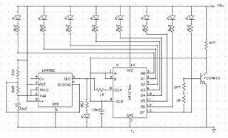
Circuit diagram :

Bridge-Rectifier-LED-Indicator-Circuit-Diagram

Bridge-Rectifier  LED Indicator Circuit Diagram

When building the schema, you’ll notice that despite its simplicity it involves fitting quite a few components to a
small printed schema board or a bit of prototyping board. That’s why we’d like to give you the tip of using a bridge rectifier, since that allows everything to be made much more compact, smaller and more tidy, and it eliminates the need for a schema board to hold the components. Besides that, you can surprise friend and foe alike, because even an old hand in the trade won’t understand the trick at first glance and will likely mumble something like “Huh?
That’s impossible.”

A bridge rectifier contains four diodes, which is exactly what you need. If you short the + and – terminals of the bridge, you create a schema with two pairs of diodes connected in parallel with oppo-site polarity. Select a bridge rectifier that can handle the current that will flow through it. In the case of a doorbell, for example, that can easily be 1 A. Select a voltage of 40 or 80 V.

Never use this schema in combination with mains voltage, due to the risk of contact with a live lead. 
Read More..

Tuesday, August 19, 2014

Simple Sixteen Stage Bi Directional LED Sequencer

The bi-directional sequencer uses a 4 bit binary up/down counter (CD4516) and two "1 of 8 line decoders"74HC138 or 74HCT138) to generate the popular "Night Rider" display. A Schmitt Trigger oscillator provides the clock signal for the counter and the rate can be adjusted with the 500K pot. Two additional Schmitt Trigger inverters are used as a SET/RESET latch to control the counting direction (up or down).

Be sure to use the 74HC14 and not the 74HCT14, the 74HCT14 may not work due to the low TTL input trigger level. When the highest count is reached (1111) the low output at pin 7 sets the latch so that the UP/DOWN input to the counter goes low and causes the counter to begin decrementing. When the lowest count is reached (0000) the latch is reset (high) so that the counter will begin incrementing on the next rising clock edge.

Simple Sixteen Stage Bi-Directional LED Sequencer

16

The three lowest counter bits (Q0, Q1, Q2) are connected to both decoders in parallel and the highest bit Q3 is used to select the appropriate decoder. The schema can be used to drive 12 volt/25 watt lamps with the addition of two transistors per lamp as shown below in the section below titled "Interfacing 5 volt CMOS to 12 volt loads".
Read More..

Sunday, August 17, 2014

Led or Lamp Flasher Circuit

This schema was designed to provide that continuous light lamps already wired into a schema, become flashing. Simply insert the schema between existing lamp and negative supply. Especially suited for car or panel pilot lights, this device can drive lamps up to 10W.


Parts:

R1 = 6.8K
R2 = 270K
R3 = 220K
D1 = 1N4002
C1 = 220uF-25V
C2 = 10uF-25V
Q1 = BC557
Q2 = BD139
B1 = Any type in the range 3-24V
B1 = Suited to the lamp adopted
LP1 = Filament Lamp 10W-3V to 24V
SW1 = On-Off Switch


Notes:

* Break lamp to negative supply connection, and then insert the schema between existing lamp connection and negative supply (respecting polarities!).
* C1 value can be varied from 100 to 1000µF or higher, in order to change flashing frequency.
* Although rather oversized, this schema can also drive any LED, providing a suitable resistor is fitted in series with the light emitting device.
* The resistor should lie in the 47R to 2K2 range, d
epending on supply voltage.
Read More..

Thursday, August 14, 2014

LED 230 V Flasher Circuit diagram

This schema operates with 230v.you can use this schema to decorate your parties.I think this will be a wonderful schema to you all.This schema was taken from my old schema book called 100 schema book.Here DIAC ER 900 and Triac BTW 11-400.

230 V Flasher Circuit diagram


Note:
  • Be careful when you deal with 230V
  • Build this schema on a PCB
  • Use only mentioned values. 


Sourced By: Freediagramdiagram4u
    Read More..